Facility Readiness Prevents Costly Civil Retrofits
Confirming electrical breaker capacity, dry air compressor CFM/m³/min, and clear ceiling height before ordering equipment prevents delivery-week surprises. Built under packaging line sizing and packaging line configurations, the chart below compiles published utility envelopes across standard turnkey configurations.
Note how heat-shrink tunnels and hot-melt case sealers dominate electrical kW demand, whereas pneumatic piston fillers, dive nozzles, and reject pushers drive compressed air volume.
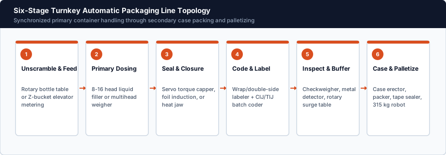
Published Utility & Dimensional Planning Envelopes
Use these baseline envelopes for preliminary plant engineering (add 20–25% compressor and breaker headroom):
| Turnkey Line Type | Typical L × W × H Envelope | Electrical Load & Supply | Compressed Air Requirement | Dominant Load Driver |
|---|---|---|---|---|
| Multihead Weigher + VFFS Line | 4.8 × 3.2 × 3.9 m (with Z-elevator) | 6.5–11 kW (220V/380V, 50/60 Hz) | 0.65 MPa @ 0.4–0.7 m³/min | Heat jaws + pneumatic gates |
| Inline Bottling + Label Line (60 BPM) | 12–16 × 2.2 × 2.3 m | 12–18 kW (220V/380V 3-phase) | 0.8 MPa @ 0.8–1.2 m³/min | Diving nozzles + capper + induction |
| Bottling + Shrink Sleeve + Case Line | 18–24 × 2.8 × 2.4 m | 28–38 kW (380V/440V 3-phase) | 0.8 MPa @ 1.2–1.6 m³/min | Electric shrink tunnel (~15–20 kW) |
| Robotic End-of-Line Case + Pallet Cell | 7.5 × 4.2 × 3.2 m (3,100 mm reach) | 8–14 kW (380V/440V 3-phase) | 0.6–0.7 MPa @ 0.5 m³/min | Servo robot axes + case erector |
Cross-check capital and operating cost impacts in our automatic packaging line cost guide.
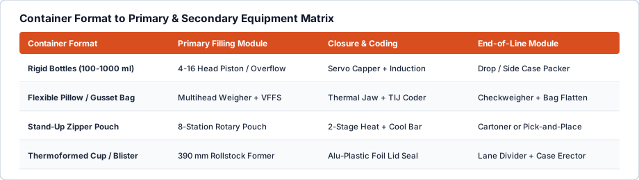
Critical Line Integration Checks
- Air Dew Point & Filtration: Supply ISO 8573-1 dry air (refrigerated dryer + 5 μm coalescing filter); wet air corrodes valve spools and causes erratic piston strokes.
- Z-Elevator Pit vs Platform: Where ceiling height is below 3.6 m, use an inclined cleated belt or low-profile multihead platform instead of a tall vertical bucket elevator.
- Dedicated Clean Ground: Provide an isolated earth ground for checkweigher load cells, induction sealers, and PLC servo cabinets.
Check Your Bay Dimensions Before Layout Freeze
Measure door opening width/height along the rigging path from loading dock to production bay.
Send your available L × W × H and voltage supply via our Project Brief.
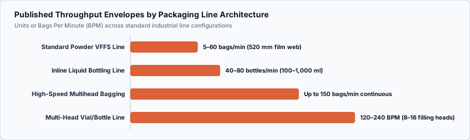
Explore related specifications in Automatic Packaging Lines, Line Configurations & Specs, and submit your container throughput targets via Project Brief.